
Electronics, telecommunications and IT
by: Daniel Olteanu (YO9CDO) , Ploiesti,
Romania 
![]()
Hello, I'm Daniel Olteanu, electronics and telecommunications engineer.
On my site you'll find some usefull circuits I've designed over the time, and someones from internet.
PIC capacimeter software, and the HEX file
RJ45 UTP/STP cable tester the emitter
RJ45 UTP/STP cable tester the receiver . You can watch this cable tester functioning in the next picture.
Dual power supply 0+30V/0-30V @1A
I have designed and built this power supply in 1992. It has double short circuit protection: first by limiting the output DC current, and the second by completely disconnecting the AC voltage at the transformer's secondary winding.
This second protection circuit it's not figured in the schematic diagram.
The AC disconnect is performed by means of an optocoupler,a timing circuit and a relay.
The picture shows the square black pushbutton, with a small green LED on it, and two yellow LEDs at the left and right.
The yellow LED ON indicates that a short circuit condition it is present on either V+ or V- section.
A few secons after the short circuit ocurred, the small green LED turns ON and indicates that the relay protection disconnected the AC.
In order to reconnect the AC the pushbutton must be pressed.
This power supply never failed since 1992. I could hardly detect any ripple at the output.
My first small superheterodyne radio receiver Medium Waves-Short Waves . I have built this receiver in 1987. Taking into account how simple it is, it has a very good selectivity and sensitivity. Here you can find the PCB I've designed for this radio receiver.
Frequency counter with PIC16F628 up to 50Mhz .
Here you can find my own PIC16F628 frequency counter project schematic. The PCB you can find it here. The HEX file you can find it here. I would like to thank to my friend VA3FGR who helped me with this frequency counter project. There are the pictures of the PCB BOTTOM and the PCB_TOP which was manufactured at PCBWAY.
DDS SIGNAL GENERATOR 0-70MHz schematic 
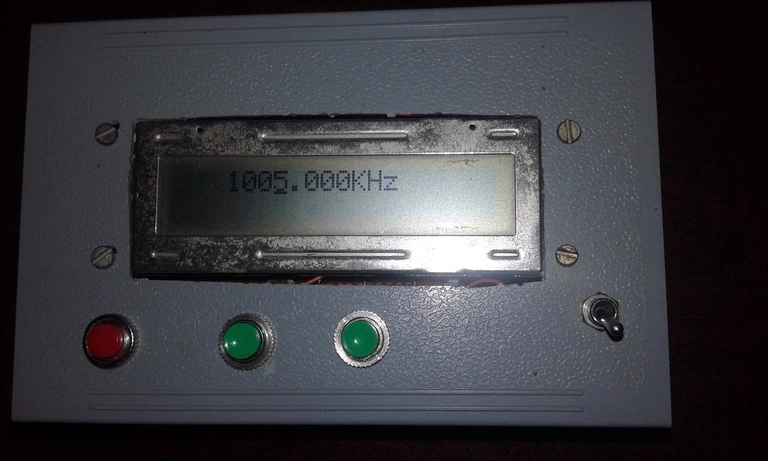
This is the design of my friend VA3FGR which I've implemented. The design uses a PIC16F876A and an AD9851 DDS module . Instead of LT1117 I've used a regular LM7805 for 5V power supply.The red button moves the cursor under each digit for digit change, the two green buttons are for UP/DOWN adjustment of digit value. The HEX file you can find it here.
www.elforum.info Best Romanian electronics forum.
SERVICES:
I install, configure, and repair Windows operating systems (7,10,11), Office 2019 package, internet access, email, fixed price 50 RON!
Contact: colt777@danolteanu.com, phone: 0732556394